Hauff Electric Pruner Cutting Blades
By: Wyley Stewart
Analysis
R.A.D.D Analysis
RADD 1:
Requirements:
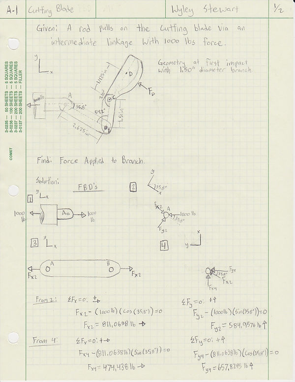
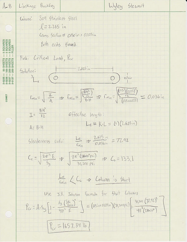
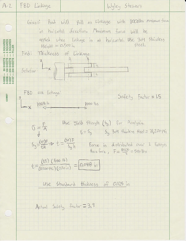
This example of R.A.D.D is of two intermediate linkages that must be able to transmit 1000 lbs force to the cutting blade arm. The linkages will be constructed of 304 Stainless Steel and will have a height of 0.500". Using a safety factor of 1.5, the thickness of the linkages will be determined.
Analysis:
The analysis of the linkage thickness can be seen Appendix A-2. The parameters used include the equation Stress=Force/Area. Also used was the yield strength of 304 Stainless Steel (31,200 psi), the area calculation for a rectangle (thickness x height), and a safety factor of 1.5. By manipulating the equation and substituting yield strength for stress, thickness can be solved for.
Design Parameters:
The design parameters for the linkages are briefly mentioned above. The height of the linkages are 0.500", they will be made of 304 Stainless Steel, and they will hold a safety factor of at least 1.5. After completing analysis using the given design parameters, it was determined that the minimum thickness for the linkages would be .048". To keep consistent with the rest of the cutting blade design, choosing a standard thickness of 0.125" will prove to be effective. By using 0.125" thickness the actual safety factor will increase to 3.9. It will be more cost efficient to produce out of same stock material as the cutting blade and anvil, rather than have to order another portion of raw stock that has a different thickness.
Documentation:
This analysis is documented in Appendix A-2.
RADD 2:
Requirements:
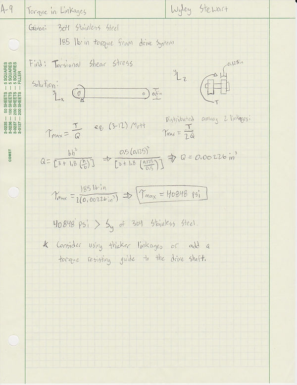
This example of R.A.D.D is of two intermediate linkages that must be able to resist 185 lb-in of torque without deforming. In normal situations the linkages would not need to resist a torsional force, however, if the ball screw got stuck and all of the rotational movement from the drive system was translated to the linkages, they would need to overcome that torsion.
Analysis:
The analysis utilized the dimensions of drawing B-3, as well as the equation ( Max torsional shear stress = T / Q ). This equation is used for non-circular cross sections that experience a torsional force. By solving for Q and using 185 lb-in as the torque value, the maximum torsional shear stress was 40848 psi. This value exceeded the value for yield strength in 304 stainless steel.
Design Parameters:
The design parameters for the linkages are briefly mentioned above. The height of the linkages are 0.500", the thickness will be 0.125”, and they will be made of 304 Stainless Steel. As a result of the analysis, it is likely that the thickness of the linkages will need to be increased. However, additional design of a torque resisting tab being added to the drive shaft has been considered.
Documentation:
This analysis is documented in Appendix A-9.
Additional Analyses